Design Of Bell Crank Lever
What is a lever?
- Bell Crank Linkage Examples
- Design Of Bell Crank Lever Diagram
- Bell Crank Lever Calculator
- Design Procedure Of Bell Crank Lever
- Bell Crank Mechanism
A lever is a rigid bar that pivots about a fulcrum. It transmits an input motion and force, (the effort) through the lever pivoting on a fulcrum to a resistance force called a load.
Load
The load is anything that is being moved by a lever.
Effort force

The effort force is the energy applied to a lever to move a load.
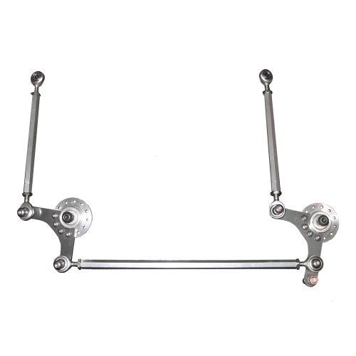
Steering law ensured by a mechanism with adjacent central joints (known as bell crank mechanism), can be identically generated by a triple central joint variant of the same.
Fulcrum
Bell Crank Linkage Examples
The fulcrum is the point at which the lever pivots. A lever may rest on a fulcrum or it may swivel on an axle, e.g. a see-saw (class 1 lever) and a wheel barrow (class 2 lever).
Classes of lever
Kingdom come deliverance do console commands disable achievements. There are three classes of levers. Ahnlab network filter driver amontdlh sys. Each class of lever has the load and effort force in specific positions relative to the fulcrum.

Design Of Bell Crank Lever Diagram
Abstract - Bell Crank Lever is important components from safety point of view since they are subjected to large amount of stresses. Hence to study the stress pattern in bell crank lever, analytical, numerical and photoelasticity methods are used. For analysis purpose virtual model of bell crank lever is prepared. Video Lecture on Problem on Bell Crank Lever from Design of Cotter Joint, Knuckle Joint,Levers and Offset Links Chapter of Design of Machine for Mechanical. A bell-crank lever consists of a long arm, 8 1 2 in. Long, and a short arm 4 in. Long, at right angles to each other. Calculate the force to be applied at right angles to the end of the long arm to overcome a resistance of 40 lbf acting at 30° to the vertical of the short arm. Handlebar lever is rotated at an angle of 90. To push the brake block against the wheel rim 2 Figure 1: Typical example of a bell crank 2 2.0 Initial Load Case. Figure 2: CAD Model of In-line Bell crank thus the results are taken to be as Figure 2 shows the design of the in-line bell crank. The bell crank is expected to be made of steel.
Class 1 lever
A Class 1 lever has the fulcrum between the load and the effort force. Torrent client download for windows 7 64 bit.
Bell Crank Lever Calculator
Class 2 lever
A Class 2 lever has the load between the fulcrum and the effort force.
Design Procedure Of Bell Crank Lever
Class 3 lever
A Class 3 has the effort force between the load and the fulcrum.

Bell Crank LeverA bell crank lever is an angled Class 1 lever. It is a Class 1 lever because the fulcrum is between the load and the effort force. The bell crank lever is used when the effort force must be at an angle, usually a right angle, to the load. |
Bell Crank Mechanism
CantileverA cantilever is a beam that is fixed at one end only. Load is applied to the unsupported end. A cantilever may be classified as a type of Class 1 lever as fulcrum is between the effort force and the load. |